In the search for the perfect DIY remote control for my soon-to-announce robot, I decided to explore IR remotes and receivers. They’re a neat little combo that help you send and receive signals without having to power or program your own external remote. If you’re interested in building some kind of remote to control whatever you’re making, look no further – you can probably repurpose the code below to meet your needs.
What you’ll need:
Arduino Uno R3 Microcontroller
Solderless Prototype PCB Breadboard
100pcs 5mm LEDs (10 colors x 10pcs) (fun colors!)
17 Values 1% Resistor Kit Assortment, 0 Ohm-1M Ohm (Pack of 525)
Infrared Wireless Remote Control IR Kit
Setup your circuits:
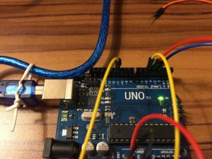
Right rail setup (pins 11, 5, 4, and 3)
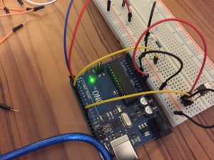
Left rail setup (5V and GND)
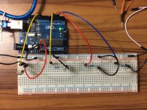
Top view of full setup
IR Receiver Setup (from left to right: data (pin 11), GND, 5V)
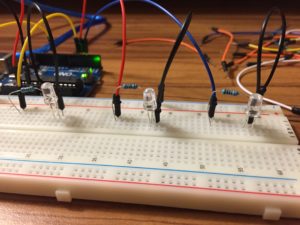
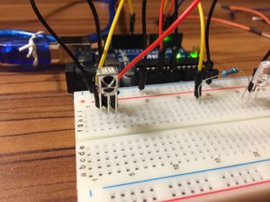
LED one to pin 5, LED two to pin 4, LED three to pin 3 from left to right.
Follow along with the images above to get everything properly setup. Pay close attention to your LED circuits – I was moving so fast when I first set this up that I was off one row with the grounding or resistor on two different circuits! The standard setup for the LED circuits should be: data in, to 22ohm resistor, to power side of LED, to ground side of LED, to ground rail. Do this three times, and you should be all set. Also, for more fun, I’d recommend using three different color LEDs – It’s definitely not essential, but it sure does make it look cooler!
After you have your hardware all wired up, let’s check out the code. Here it is:
// By MichaelBryanRoss, with some help from Elegoo

// libraries included
#include <IRremote.h>

// pin declarations
int RECV_PIN = 11;
int led1 = 5;
int led2 = 4;
int led3 = 3;

// decimal input values to match from reciever
long int num1 = 16724175;
long int num2 = 16718055;
long int num3 = 16743045;

// variables that will change
int led1State = 0;
int led2State = 0;
int led3State = 0;

// object declaration
IRrecv irrecv(RECV_PIN);
decode_results results;

void setup(){
  Serial.begin(9600);
  irrecv.enableIRIn();
  irrecv.blink13(true);
  pinMode(led1, OUTPUT);
  pinMode(led2, OUTPUT);
  pinMode(led3, OUTPUT);
}

void loop(){
  if (irrecv.decode(&results)){
    Serial.println(results.value);
      if (results.value == num1 && led1State == 0){
        digitalWrite(led1, HIGH);
        led1State = 1;
      } else if (results.value == num1 && led1State == 1) {
        digitalWrite(led1, LOW);
        led1State = 0;
      }
       if (results.value == num2 && led2State == 0){
        digitalWrite(led2, HIGH);
        led2State = 1;
      } else if (results.value == num2 && led2State == 1) {
        digitalWrite(led2, LOW);
        led2State = 0;
      }
       if (results.value == num3 && led3State == 0){
        digitalWrite(led3, HIGH);
        led3State = 1;
      } else if (results.value == num3 && led3State == 1) {
        digitalWrite(led3, LOW);
        led3State = 0;
      }
    irrecv.resume();
  }
}
Let’s quickly review the code above, but let’s skip to the void loop (everything else is setup, but let me know if you need any there and I’d be happy to review). The first call to:
if (irrecv.decode(&results)){
Serial.println(results.value);
This is effectively a call to the library that says, “Hey, if the IR Receiver detects something, grab the results, and print it to the serial terminal.” If we really wanted to, we could skip the second line of code. However, it adds visibility by at least showing you in the terminal what you’re receiving. I find this super useful to better seeing what’s happening as you run the code.
The next part is where all the fun happens:
      if (results.value == num1 && led1State == 0){
        digitalWrite(led1, HIGH);
        led1State = 1;
      } else if (results.value == num1 && led1State == 1) {
        digitalWrite(led1, LOW);
        led1State = 0;
      }
       if (results.value == num2 && led2State == 0){
        digitalWrite(led2, HIGH);
        led2State = 1;
      } else if (results.value == num2 && led2State == 1) {
        digitalWrite(led2, LOW);
        led2State = 0;
      }
       if (results.value == num3 && led3State == 0){
        digitalWrite(led3, HIGH);
        led3State = 1;
      } else if (results.value == num3 && led3State == 1) {
        digitalWrite(led3, LOW);
        led3State = 0;
      }
In this section we essentially tell the system what to do when we see specific decimal values. We also introduce an “LED state” that basically allows us to remember if the LED is on or off. Tracking the state allows us to then write the code to simply turn on or turn off the LED based upon multiple button presses (There are probably other more memory efficient ways to do this, but this is just the approach that I chose to go with).
If you’re trying to turn something on or off based on the decimal value received from an IR remote, you should be able to repurpose this code accordingly. If you don’t need to maintain states, just delete those parts!
This last bit is simple:
irrecv.resume();
It simple tells the receiver to continue listening for more commands.
Well, that’s it! You should now be well on your way to receiving and working with IR signals. Make sure to check out the video if you want to see the final results: