Product, Business, and More

Category: ardunio

Using IR remotes and receivers to turn on (or off) LEDs

In the search for the perfect DIY remote control for my soon-to-announce robot, I decided to explore IR remotes and receivers. They’re a neat little combo that help you send and receive signals without having to power or program your own external remote. If you’re interested in building some kind of remote to control whatever you’re making, look no further – you can probably repurpose the code below to meet your needs.

What you’ll need:

Arduino Uno R3 Microcontroller

Solderless Prototype PCB Breadboard

120pcs Multicolored Dupont Wire 40pin Male to Female, 40pin Male to Male, 40pin Female to Female Breadboard Jumper Wires

100pcs 5mm LEDs (10 colors x 10pcs) (fun colors!)

17 Values 1% Resistor Kit Assortment, 0 Ohm-1M Ohm (Pack of 525)

Infrared Wireless Remote Control IR Kit

Setup your circuits:
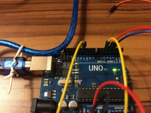
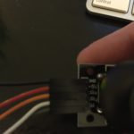
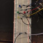
Right rail setup (pins 11, 5, 4, and 3)
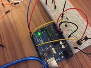
Right rail setup (pins 11, 5, 4, and 3)

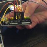
Left rail setup (5V and GND)
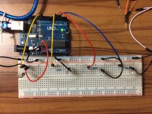
Left rail setup (5V and GND)

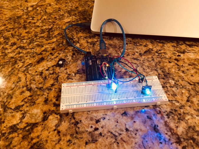
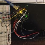
Top view of full setup
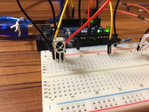
Top view of full setup

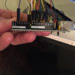
IR Receiver Setup (from left to right: data (pin 11), GND, 5V)
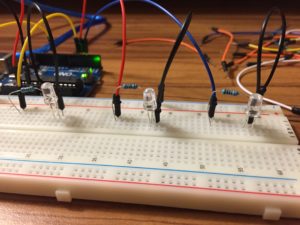
IR Receiver Setup (from left to right: data (pin 11), GND, 5V)

LED one to pin 5, LED two to pin 4, LED three to pin 3 from left to right.

LED one to pin 5, LED two to pin 4, LED three to pin 3 from left to right.

Follow along with the images above to get everything properly setup. Pay close attention to your LED circuits – I was moving so fast when I first set this up that I was off one row with the grounding or resistor on two different circuits! The standard setup for the LED circuits should be: data in, to 22ohm resistor, to power side of LED, to ground side of LED, to ground rail. Do this three times, and you should be all set. Also, for more fun, I’d recommend using three different color LEDs – It’s definitely not essential, but it sure does make it look cooler!

After you have your hardware all wired up, let’s check out the code. Here it is:

// By MichaelBryanRoss, with some help from Elegoo

// libraries included
#include <IRremote.h>

// pin declarations  
int RECV_PIN = 11;
int led1 = 5;
int led2 = 4;
int led3 = 3;

// decimal input values to match from reciever 
long int num1 = 16724175;
long int num2 = 16718055;
long int num3 = 16743045;

// variables that will change
int led1State = 0;
int led2State = 0;
int led3State = 0;

// object declaration
IRrecv irrecv(RECV_PIN);
decode_results results;

void setup(){
  Serial.begin(9600);
  irrecv.enableIRIn();
  irrecv.blink13(true);
  pinMode(led1, OUTPUT);
  pinMode(led2, OUTPUT);
  pinMode(led3, OUTPUT);
}

void loop(){
  if (irrecv.decode(&results)){
    Serial.println(results.value);
      if (results.value == num1 && led1State == 0){
        digitalWrite(led1, HIGH);
        led1State = 1;
      } else if (results.value == num1 && led1State == 1) {
        digitalWrite(led1, LOW);
        led1State = 0;
      }
       if (results.value == num2 && led2State == 0){
        digitalWrite(led2, HIGH);
        led2State = 1;
      } else if (results.value == num2 && led2State == 1) {
        digitalWrite(led2, LOW);
        led2State = 0;
      }
       if (results.value == num3 && led3State == 0){
        digitalWrite(led3, HIGH);
        led3State = 1;
      } else if (results.value == num3 && led3State == 1) {
        digitalWrite(led3, LOW);
        led3State = 0;
      }
    irrecv.resume();
  }
}

Let’s quickly review the code above, but let’s skip to the void loop (everything else is setup, but let me know if you need any there and I’d be happy to review). The first call to:

if (irrecv.decode(&results)){
Serial.println(results.value);

This is effectively a call to the library that says, “Hey, if the IR Receiver detects something, grab the results, and print it to the serial terminal.” If we really wanted to, we could skip the second line of code. However, it adds visibility by at least showing you in the terminal what you’re receiving. I find this super useful to better seeing what’s happening as you run the code.

The next part is where all the fun happens:

      if (results.value == num1 && led1State == 0){
        digitalWrite(led1, HIGH);
        led1State = 1;
      } else if (results.value == num1 && led1State == 1) {
        digitalWrite(led1, LOW);
        led1State = 0;
      }
       if (results.value == num2 && led2State == 0){
        digitalWrite(led2, HIGH);
        led2State = 1;
      } else if (results.value == num2 && led2State == 1) {
        digitalWrite(led2, LOW);
        led2State = 0;
      }
       if (results.value == num3 && led3State == 0){
        digitalWrite(led3, HIGH);
        led3State = 1;
      } else if (results.value == num3 && led3State == 1) {
        digitalWrite(led3, LOW);
        led3State = 0;
      }

In this section we essentially tell the system what to do when we see specific decimal values. We also introduce an “LED state” that basically allows us to remember if the LED is on or off. Tracking the state allows us to then write the code to simply turn on or turn off the LED based upon multiple button presses (There are probably other more memory efficient ways to do this, but this is just the approach that I chose to go with).

If you’re trying to turn something on or off based on the decimal value received from an IR remote, you should be able to repurpose this code accordingly. If you don’t need to maintain states, just delete those parts!

This last bit is simple:

    irrecv.resume();

It simple tells the receiver to continue listening for more commands.

Well, that’s it! You should now be well on your way to receiving and working with IR signals. Make sure to check out the video if you want to see the final results:
Electricity Basics – Potentiometers!

Potentiometers are sweet! Basically, they allow you to set a variable resistance to be applied to your circuit – which allows you to adjust the total resistance on the fly. This is most commonly used with LED displays, but there are many other use cases, too. Check out how cool they are:

The Joy of Joysticks: Reading Joystick Input with an Arduino

So I haven’t posted about it yet, but I’ve been working on a car-like robot. It’s a bigger project, and I’ll post about it soon. However, for that project I wanted to learn how to make a remote of sorts to direct the car around the room – so I purchased a joystick chip, and wired up some LEDs to learn how use the analog input to do something fun.

What you’ll need:

Arduino JoyStick

Multicolored Wire Kit (40pin Male to Female, 40pin Male to Male, 40pin Female to Female Jumper Wires)

Breadboards

Arduino UNO R3 Board

Setup your circuits:

I’m not going to go into deep detail on how to wire the LED circuits, but drop a comment if you can’t figure it out and I’d be happy to help. The new piece for this tutorial is the joystick. The joystick breakout has five pins: 1) ground, 2) 5 volt power, 3) x pin, 4) y pin, and 5) switch pin. The x and y pins are analog, while the switch is digital. If you don’t know the difference between these two, no problem – you can learn about the differences here.

Once you have this all wired up, here’s the code that you’ll want to write in your scratch:


//michaelbryanross

// define pins
const int SW_pin = 2; // digital, switch
const int X_pin = 0; // analog, X output
const int Y_pin = 1; // analog, Y output
const int blueLed = 12;
const int greenLed = 11;
const int redLed = 10;
const int yellowLed = 9;
const int whiteLed = 8;

// setup pins
void setup() {
  pinMode(SW_pin, INPUT);
  pinMode(blueLed, OUTPUT);
  pinMode(yellowLed, OUTPUT);
  pinMode(redLed, OUTPUT);
  pinMode(greenLed, OUTPUT);
  pinMode(whiteLed, OUTPUT);
  digitalWrite(SW_pin, HIGH);
  Serial.begin(9600);
}

// main loop
void loop() {
  //prints some stuff to read out in the serial monitor (skip this part if you don't want to see the output)
  Serial.print("Switch:  ");
  Serial.print(digitalRead(SW_pin));
  Serial.print("\n");
  Serial.print("X-axis: ");
  Serial.print(analogRead(X_pin));
  Serial.print("\n");
  Serial.print("Y-axis: ");
  Serial.println(analogRead(Y_pin));
  Serial.print("\n\n");

  // LED logic
  if(analogRead(Y_pin) == 1023)
  {
    digitalWrite(yellowLed, HIGH);
    delay(500);
    digitalWrite(yellowLed, LOW);
  } else if (analogRead(Y_pin) == 0) {
    digitalWrite(blueLed, HIGH);
    delay(500);
    digitalWrite(blueLed, LOW);
  } else if (analogRead(X_pin) == 1023) {
    digitalWrite(redLed, HIGH);
    delay(500);
    digitalWrite(redLed, LOW);
  } else if (analogRead(X_pin) == 0) {
    digitalWrite(greenLed, HIGH);
    delay(500);
    digitalWrite(greenLed, LOW);
  } else if (digitalRead(SW_pin) == 0) {
    digitalWrite(whiteLed, HIGH);
    delay(500);
  } else {
    digitalWrite(blueLed, LOW);
    digitalWrite(yellowLed, LOW);
    digitalWrite(redLed, LOW);
    digitalWrite(greenLed, LOW);
    digitalWrite(whiteLed, LOW);
  }
  delay(100);
}

If this doesn’t make sense, I would recommend running the code without the LEDs first, and looking at the serial monitor. If you use the serial section above, you’ll be able to see the different outputs that the joystick produces. After you see those values, the else/if block should make a little more sense.

Here’s the thing in action:

As always, please let me know if you have any questions!

Every Zillow Group Brand in RGB LEDs

How to Blink Every Zillow Group Brand in RGB LEDs

In previous posts I’ve been using standard LEDs – however, now we’re cooking with gas… welcome, RGB LEDs. These LEDs are way cooler than standard LEDs, because this one LED actually has three different LEDs inside it. As the name suggests, there’s one red, green and blue LED in each RGB LED. You can then use Pulse Width Modulation (PWM) and some simple code to have that one LED become any RGB color under the sun!

I was going to use these LEDs to cycle through every NFL team’s primary and secondary colors, but then I thought… what’s cooler than the NFL? Zillow Group, of course! So, in the code below I filter through every Zillow Group brand’s primary and secondary color. If Zillow Group isn’t your thing (even though it should be) you can use this code to filter through any list of two-color organizations that you’d like – just replace the ZG color values with the color values of your choosing.

What you’ll need:

Arduino UNO R3 (Kit, but can just get the Ardunio)

Round Head Common Cathode RGB LED (50 Pack – only need 2 for this tutorial)

40pin M to F, 40pin M to M, 40pin F to F Ribbon Cables Kit

220 Ohm Resistors (Pack of 25)

Breadboard(s)

Wire the Circuits

The circuits are pretty simple – just make sure that you know if you’re working with an cathode LED or an anode LED (the ones I used are cathode, and so is the link above). The most important part is to make sure that you connect to a pin that is capable of PWM (I wont write about PWM here, but check it out on Wikipedia if you want to learn more about what this is). In this tutorial I’ve used pins 3, 5, 6, 9, 10, and 11 (some boards have a “~” indicating that the pin is PWM compatible).

Here are a few different angles of my setup:

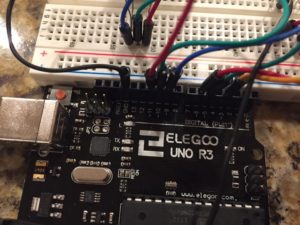
RGB LED Circuits, Pin View

RGB LED Circuits, Pin View

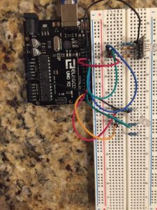
RGB LED Circuits, Top View

RGB LED Circuits, Top View

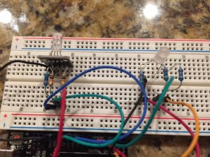
RGB LED Circuits, Breadboard View

RGB LED Circuits, Breadboard View

The Code

//MichaelBryanRoss

// Define Pins
int redPin = 11;
int greenPin = 10;
int bluePin = 9;

int redPin2 = 6;
int greenPin2 = 5;
int bluePin2 = 3;

void setup()
{
pinMode(redPin, OUTPUT);
pinMode(greenPin, OUTPUT);
pinMode(bluePin, OUTPUT);

pinMode(redPin2, OUTPUT);
pinMode(greenPin2, OUTPUT);
pinMode(bluePin2, OUTPUT);
}

// main loop
void loop()
{
  color(255,255,255,0,116,223); //Zillow
  color(255,255,255,0,161,106); //Trulia
  color(255,255,255,33,47,97); //StreetEasy
  color(76,75,77,234,63,51); //RealEstate.com(gray and red)
  color(238,123,51,77,174,198); //Naked Apartments(orange and teal) 
  color(237,118,81,248,211,101); //hotpads(orange-red and yellow)
  color(0,0,0,255,255,255); //Outeast 
}

void color(int red, int green, int blue, int red2, int green2, int blue2 )
{
  analogWrite(redPin, red);
  analogWrite(greenPin, green);
  analogWrite(bluePin, blue);
  analogWrite(redPin2, red2);
  analogWrite(greenPin2, green2);
  analogWrite(bluePin2, blue2);
  delay(1000);
}

*Note on the code – this is not python code. It’s C – however, the wordpress plugin I’m using for code inserts does not have a setup for C, so I just kept it stylized as Python).

There you go! Compile the code and run it on your Arduino and you now have a rotating blinking of all the ZG brand’s colors!

PS – this post does not in any way reflect Zillow Group values or opinions.

PPS – Spencer, if you’re reading this… you made my day! (and please know that past Hackweeks are exactly what got a Program Manager interested in learning to code hardware. )


© 2024 Michael Bryan Ross

Theme by Anders NorenUp ↑