So I haven’t posted about it yet, but I’ve been working on a car-like robot. It’s a bigger project, and I’ll post about it soon. However, for that project I wanted to learn how to make a remote of sorts to direct the car around the room – so I purchased a joystick chip, and wired up some LEDs to learn how use the analog input to do something fun.
What you’ll need:
Setup your circuits:
-
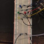
- LED circuits
-
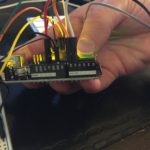
- Everything Wired Up, Joystick to LEDs
-
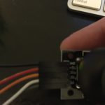
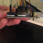
- Joystick Pins
-
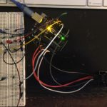
- Joystick to LEDs, Power and Analog Pins
-
- Joystick to LEDs, Digital Pins
I’m not going to go into deep detail on how to wire the LED circuits, but drop a comment if you can’t figure it out and I’d be happy to help. The new piece for this tutorial is the joystick. The joystick breakout has five pins: 1) ground, 2) 5 volt power, 3) x pin, 4) y pin, and 5) switch pin. The x and y pins are analog, while the switch is digital. If you don’t know the difference between these two, no problem – you can learn about the differences here.
Once you have this all wired up, here’s the code that you’ll want to write in your scratch:
//michaelbryanross

// define pins
const int SW_pin = 2; // digital, switch
const int X_pin = 0; // analog, X output
const int Y_pin = 1; // analog, Y output
const int blueLed = 12;
const int greenLed = 11;
const int redLed = 10;
const int yellowLed = 9;
const int whiteLed = 8;

// setup pins
void setup() {
  pinMode(SW_pin, INPUT);
  pinMode(blueLed, OUTPUT);
  pinMode(yellowLed, OUTPUT);
  pinMode(redLed, OUTPUT);
  pinMode(greenLed, OUTPUT);
  pinMode(whiteLed, OUTPUT);
  digitalWrite(SW_pin, HIGH);
  Serial.begin(9600);
}

// main loop
void loop() {
  //prints some stuff to read out in the serial monitor (skip this part if you don't want to see the output)
  Serial.print("Switch:  ");
  Serial.print(digitalRead(SW_pin));
  Serial.print("\n");
  Serial.print("X-axis: ");
  Serial.print(analogRead(X_pin));
  Serial.print("\n");
  Serial.print("Y-axis: ");
  Serial.println(analogRead(Y_pin));
  Serial.print("\n\n");

  // LED logic
  if(analogRead(Y_pin) == 1023)
  {
    digitalWrite(yellowLed, HIGH);
    delay(500);
    digitalWrite(yellowLed, LOW);
  } else if (analogRead(Y_pin) == 0) {
    digitalWrite(blueLed, HIGH);
    delay(500);
    digitalWrite(blueLed, LOW);
  } else if (analogRead(X_pin) == 1023) {
    digitalWrite(redLed, HIGH);
    delay(500);
    digitalWrite(redLed, LOW);
  } else if (analogRead(X_pin) == 0) {
    digitalWrite(greenLed, HIGH);
    delay(500);
    digitalWrite(greenLed, LOW);
  } else if (digitalRead(SW_pin) == 0) {
    digitalWrite(whiteLed, HIGH);
    delay(500);
  } else {
    digitalWrite(blueLed, LOW);
    digitalWrite(yellowLed, LOW);
    digitalWrite(redLed, LOW);
    digitalWrite(greenLed, LOW);
    digitalWrite(whiteLed, LOW);
  }
  delay(100);
}
If this doesn’t make sense, I would recommend running the code without the LEDs first, and looking at the serial monitor. If you use the serial section above, you’ll be able to see the different outputs that the joystick produces. After you see those values, the else/if block should make a little more sense.
Here’s the thing in action:
As always, please let me know if you have any questions!